Custom PCB · Motor Control

FOC NEMA17 Stepper Motor Driver
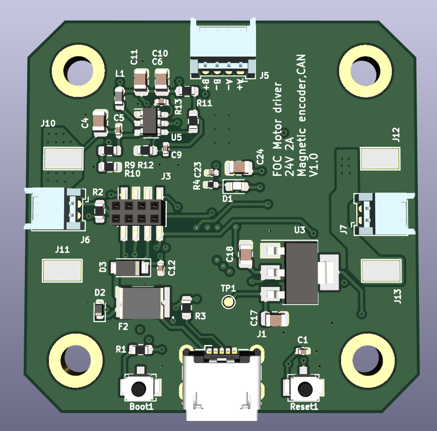
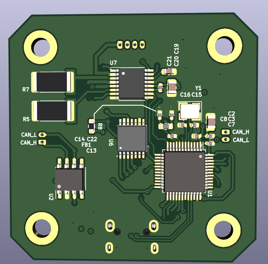
KiCad STM32F103CBTx DRV8844 FOC CAN bus Magnetic encoder 4-layer PCB
Board revisionV1.0
Input24 V, 2 A rated
MCUSTM32F103CBTx (Arm Cortex-M3)
Motor driverTI DRV8844PWPR dual H-bridge, HTSSOP-16 PowerPAD
Control schemeField-oriented control (FOC), closed loop
Position feedbackExternal magnetic encoder, 4-pin differential header (J5)
Current sensingDual TI INA181 shunt amplifiers, one per motor phase
Bus interfaceNXP TJA1051T-3 CAN transceiver
Power stageTPS54202DDC buck converter + AMS1117 LDO for logic rails
ProtectionPRTR5V0U2X ESD array, SMBJ26A TVS, PMEG6020AELR Schottky, resettable polyfuse
ProgrammingUSB Micro-B, BOOT1 / RESET1 buttons for DFU entry
Layout4-layer, mounted via 4x corner holes for direct NEMA17 fitment

Overview

This board is a compact closed-loop driver for a NEMA17 stepper motor, built for a robotic arm project. It runs field-oriented control on an STM32F103, reading phase current through two INA181 amplifiers and rotor position from an external magnetic encoder, so the motor can be commanded smoothly instead of driven open loop.

  • DRV8844 H-bridge drives both motor phases directly from the 24V rail.
  • Per-phase current sensing feeds the FOC control loop running on the STM32.
  • CAN transceiver lets the board sit on a shared bus with other joints in a multi-axis arm.
  • On-board buck and LDO regulators generate the 5V and 3.3V logic rails from the 24V input.
  • ESD and TVS protection on the CAN and USB lines for robustness outside a bench setting.
  • USB Micro-B plus BOOT1/RESET1 buttons for firmware flashing without a separate programmer.

Schematic & PCB

Live KiCad source, rendered in the browser via KiCanvas. Use the panel on the right of the viewer to switch between the schematic and the PCB layout, pan and zoom, and inspect individual nets and footprints.

Rendered client-side from the original .kicad_sch / .kicad_pcb files, no export or screenshot.

Downloads