Mechanical Design · Control Systems · CAD

Furuta Pendulum

Onshape 3D CAD Furuta pendulum Assembly Mates NEMA17 stepper AS5600 encoder Animation Simscape Multibody STM32 Nucleo-F446RE X-NUCLEO-IHM01A1 STM32CubeIDE

The pendulum model in the Simscape Mechanics Explorer.

Controller boardSTM32 Nucleo-F446RE
Motor driverX-NUCLEO-IHM01A1 stepper driver expansion board
Motor17HE12-1204S NEMA17 stepper
SensorAS5600 magnetic encoder
DevelopmentSTM32CubeIDE

Overview

A Furuta pendulum, also called a rotary inverted pendulum, modelled in Onshape. I built the parts, combined them into an assembly with mates, and animated the motion.

  • A stand holds a 17HE12-1204S NEMA17 stepper motor, which turns the encoder mount.
  • The pendulum is a bent arm that pivots in the encoder mount and carries a mass at its tip.
  • An AS5600 magnetic encoder on the encoder mount reads the pendulum angle.
  • 8 part instances and 8 mates in the full assembly.

Simscape Multibody model
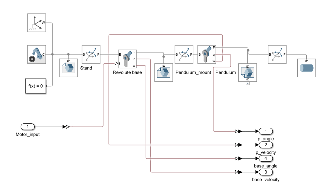
Simscape Multibody diagram of the pendulum: world frame and solver configuration, the stand, a torque-driven revolute joint for the base, the pendulum mount, a second revolute joint for the pendulum and a tip mass. A Motor_input port drives the base joint, and the pendulum angle and velocity and base angle and velocity are outputs.
The multibody model. A motor torque drives the base joint, and the model outputs the pendulum and base angles and velocities.

Hardware

The built pendulum on hardware.

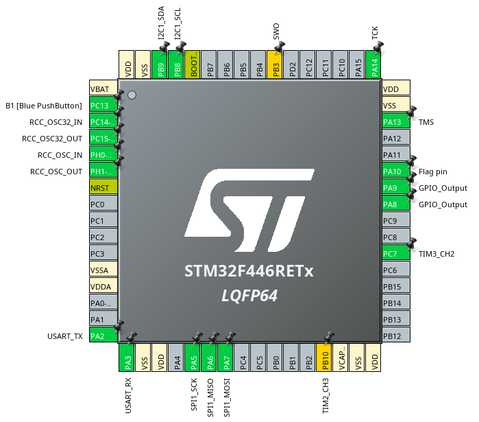
STM32CubeIDE pinout view of the STM32F446RET6 in LQFP64: SPI1 on PA5, PA6 and PA7, a flag pin on PA10, GPIO outputs on PA8 and PA9, TIM3_CH2 on PC7, TIM2_CH3 on PB10, I2C1 on PB8 and PB9, USART2 on PA2 and PA3, and the blue push button on PC13
Pin configuration of the STM32F446RE in STM32CubeIDE. SPI1 and the flag pin connect to the IHM01A1 driver, and I2C1 reads the AS5600 encoder.